This page is a work in progress, and will soon include instructions for FLdigi, APRSDroid, and WSJTX
NOTE – For AIOB V1.0 (any AIOBs ordered before 08/01/2024) there is a hardware issue affecting serial tx. Please read here for the fix: https://w1btr.com/index.php/aiob-v1-0-serial-data-fix/ If your board has a 5V RRX pad, you have a v 1.0 board.
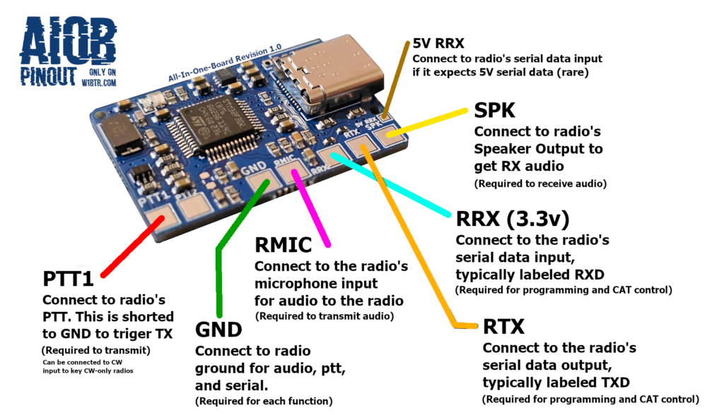
Ground
The AIOB utilizes shared ground, with one pad on the top and one pad on the bottom for easier interfacing.
This ground source is shared between PTT, RMIC (radio microphone), and SPK (Speaker), as well as the ground for serial communication so it is recommended to solder all four (4) ground wires together at the end.
PTT
This is the primary PTT source which will be shorted to ground when it is triggered by the AIOB. While not technically required, it is more reliable than VOX. This should be connected to the PTT input on the radio.
PTT2 is designed for dual-ptt radios, of which there are few. However, some users have also used it as a dedicated CW input. Where PTT1 is triggered by DTR, PTT2 is triggered by RTS by default.
RMIC
As with the rest of the pinout, the “mic” in question is from the radio’s perspective. Your computer will see it as a speaker output, and this should be connected to the microphone input on the radio.
SPK
This should be connected to the radio’s speaker output (or headphone jack). The computer will see this as a microphone / audio input into the PC, and will stream audio the radio is receiving.
RRX & RTX
These are the pins for TX and RX data from the radio’s perspective. The AIOB sends serial data out the RRX pad, and receives from the radio on RTX.
At this time, serial communication with radios which consolidate TX and RX data to one connection is not supported.
